- 您现在的位置:买卖IC网 > Sheet目录475 > MAX9993EVKIT (Maxim Integrated)EVAL KIT FOR MAX9993
�� �
�
�MAX9993� Evaluation� Kit�
�Quick� Start�
�The� MAX9993� EV� kit� is� fully� assembled� and� factory� test-�
�ed.� Follow� the� instructions� in� the� Connections� and�
�Setup� section� for� proper� device� evaluation.�
�Test� Equipment� Required�
�Table� 1� lists� the� equipment� required� to� verify� the� opera-�
�tion� of� the� MAX9993� EV� kit.� It� is� intended� as� a� guide�
�only,� and� some� substitutions� are� possible.�
�Connections� and� Setup�
�This� section� provides� a� step-by-step� guide� to� testing�
�the� basic� functionality� of� the� EV� kit.� As� a� general� pre-�
�9)� Set� DC� supply� to� +5.0V,� and� set� a� current� limit�
�around� 250mA� if� possible.� Disable� the� output� volt-�
�age� and� connect� the� supply� to� the� EV� kit� through�
�the� ammeter.� Enable� the� supply.� Re-adjust� the� sup-�
�ply� to� get� +5.0V� at� the� EV� kit.� There� will� be� a� voltage�
�drop� across� the� ammeter� when� the� mixer� is� drawing�
�current.�
�10)� Select� LO1� by� connecting� LOSEL� (TP3)� to� GND.�
�11)� Enable� the� LO� and� the� RF� sources.�
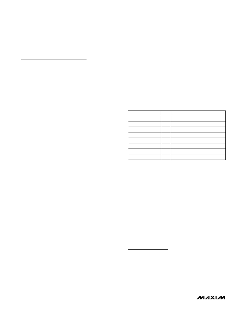
�Table� 1.� Test� Equipment�
�caution� to� prevent� damaging� the� outputs� by� driving�
�high-VSWR� loads,� do� not� turn� on� DC� power� or� RF�
�signal� generators� until� all� connections� are� made.�
�This� procedure� is� specific� to� operation� in� the� U.S.� PCS�
�band� (reverse� channel:� 1850MHz� to� 1910MHz),� low-�
�side� injected� LO� for� a� 200MHz� IF.� Choose� the� test� fre-�
�quency� based� on� the� particular� system� ’� s� frequency�
�plan,� and� adjust� the� following� procedure� accordingly.�
�See� Figure� 1� for� the� mixer� test� setup� diagram.�
�1)� Calibrate� the� power� meter� for� 1700MHz.� For� safety�
�EQUIPMENT�
�HP� E3631A�
�Fluke� 75� Series� II�
�HP/Agilent� 8648B�
�HP� 437B�
�HP� 8482A�
�HP� 8561�
�3dB� Pad�
�50� ?� Termination�
�QTY�
�1�
�1�
�3�
�1�
�1�
�1�
�4�
�1�
�DESCRIPTION�
�DC� power� supply�
�Digital� multimeter� (ammeter)�
�RF� signal� generators�
�RF� power� meter�
�High-power� sensor� (power� head)�
�Spectrum� analyzer�
�3dB� attenuators�
�50� ?� (1W)� termination�
�margin,� use� a� power� sensor� rated� to� at� least�
�+20dBm,� or� use� padding� to� protect� the� power� head�
�as� necessary.�
�2)� Connect� 3dB� pads� to� the� DUT� ends� of� each� of� the�
�three� RF� signal� generators� ’� SMA� cables.� This�
�padding� improves� VSWR,� and� reduces� the� errors�
�due� to� mismatch.�
�3)� Use� the� power� meter� to� set� the� RF� signal� generators�
�according� to� the� following:�
�?� RF� signal� source:� -5dBm� into� DUT� at� 1900MHz�
�(this� will� be� about� -2dBm� before� the� 3dB� pad)�
�?� LO1� signal� source:� +3dBm� into� DUT� at� 1700MHz�
�(this� will� be� about� +6dBm� before� the� 3dB� pad)�
�?� LO2� signal� source:� +3dBm� into� DUT� at� 1701MHz�
�(this� will� be� about� +6dBm� before� the� 3dB� pad)�
�4)� Disable� the� signal� generator� outputs.�
�5)� Connect� the� RF� source� (with� pad)� to� RF� IN.�
�6)� Connect� the� LO1� and� LO2� signal� sources� to� the� EV�
�kit� LO� inputs.�
�7)� Measure� loss� in� the� 3dB� pad� and� the� cable� that� will�
�be� connected� to� IF� OUT.� Losses� are� frequency�
�dependent,� so� test� this� at� 200MHz� (the� IF� frequen-�
�cy).� Use� this� loss� as� an� offset� in� all� output�
�power/gain� calculations.�
�8)� Connect� this� 3dB� pad� to� the� EV� kit� ’� s� IF� OUT� connec-�
�tor,� and� connect� a� cable� from� the� pad� to� the� spec-�
�trum� analyzer.�
�Testing� the� Mixer�
�Adjust� the� center� and� span� of� the� spectrum� analyzer� to�
�observe� the� IF� output� tone� at� 200MHz.� The� level� should�
�be� about� +0.5dBm� (8.5dB� conversion� gain,� 3dB� pad�
�loss).� There� will� also� be� a� tone� at� 199MHz,� which� is� due� to�
�the� LO� signal� applied� to� LO2.� The� amount� of� suppression�
�between� the� 200MHz� and� 199MHz� signals� is� the� switch�
�isolation.� The� spectrum� analyzer� ’� s� absolute� magnitude�
�accuracy� is� typically� no� better� than� ±1dB.� Use� the� power�
�meter� to� get� an� accurate� output� power� measurement.�
�Disconnect� the� GND� connection� to� LOSEL.� It� will� be�
�pulled� high� by� a� pullup� resistor� on� the� board,� selecting�
�LO2.� Observe� that� the� 199MHz� signal� increases� while�
�the� 200MHz� decreases.�
�Reconfigure� the� test� setup� using� a� combiner� or� hybrid�
�to� sum� the� two� LO� inputs� to� do� a� 2-tone� IP3� measure-�
�ment� if� desired.� Terminate� the� unused� LO� input� in� 50� ?� .�
�Detailed� Description�
�The� MAX9993� is� a� highly� integrated� downconverter.� RF�
�and� LO� baluns� are� integrated� on-chip,� as� well� as� an� LO�
�buffer� and� a� SPDT� LO� input� select� switch.� The� EV� kit� cir-�
�cuit� consists� mostly� of� supply� decoupling� capacitors� and�
�DC-blocking� capacitors,� allowing� for� a� simple� design-in.�
�Supply� Decoupling� Capacitors�
�Capacitors� C2,� C6,� and� C7� are� 22pF� (±5%)� high-fre-�
�quency� supply� decoupling� capacitors� necessary� to� keep�
�2�
�_______________________________________________________________________________________�
�发布紧急采购,3分钟左右您将得到回复。
相关PDF资料
MAX9994ETP+T
IC MIXER DOWN CONV 20-TQFN
MAX9994EVKIT
EVAL KIT FOR MAX9994
MAX9995ETX+T
IC MIXER DOWN CONV 36-TQFN
MAX9995EVKIT
EVAL KIT FOR MAX9995
MAX9996ETP+D
IC MIXER DOWN CONV 20-TQFN
MAX9996EVKIT
EVAL KIT FOR MAX9996
MC-7831-AZ
IC PUSH-PULL AMP 870MHZ H02
MC-7832-AZ
IC PUSH-PULL AMP 870MHZ H02
相关代理商/技术参数
MAX9994ETP
功能描述:上下转换器 SiGe 1700-2200MHz Downconversion Mixer RoHS:否 制造商:Texas Instruments 产品:Down Converters 射频:52 MHz to 78 MHz 中频:300 MHz LO频率: 功率增益: P1dB: 工作电源电压:1.8 V, 3.3 V 工作电源电流:120 mA 最大功率耗散:1 W 最大工作温度:+ 85 C 安装风格:SMD/SMT 封装 / 箱体:PQFP-128
MAX9994ETP+
功能描述:上下转换器 SiGe 1700-2200MHz Downconversion Mixer RoHS:否 制造商:Texas Instruments 产品:Down Converters 射频:52 MHz to 78 MHz 中频:300 MHz LO频率: 功率增益: P1dB: 工作电源电压:1.8 V, 3.3 V 工作电源电流:120 mA 最大功率耗散:1 W 最大工作温度:+ 85 C 安装风格:SMD/SMT 封装 / 箱体:PQFP-128
MAX9994ETP+D
制造商:Maxim Integrated Products 功能描述:UP/DOWN CONV MIXER 5V 2.2GHZ 20TQFN EP - Rail/Tube
MAX9994ETP+T
功能描述:上下转换器 SiGe 1700-2200MHz Downconversion Mixer RoHS:否 制造商:Texas Instruments 产品:Down Converters 射频:52 MHz to 78 MHz 中频:300 MHz LO频率: 功率增益: P1dB: 工作电源电压:1.8 V, 3.3 V 工作电源电流:120 mA 最大功率耗散:1 W 最大工作温度:+ 85 C 安装风格:SMD/SMT 封装 / 箱体:PQFP-128
MAX9994ETP+TD
制造商:Maxim Integrated Products 功能描述:UP/DOWN CONV MIXER 5V 2.2GHZ 20TQFN EP - Tape and Reel
MAX9994ETP-T
功能描述:上下转换器 SiGe 1700-2200MHz Downconversion Mixer RoHS:否 制造商:Texas Instruments 产品:Down Converters 射频:52 MHz to 78 MHz 中频:300 MHz LO频率: 功率增益: P1dB: 工作电源电压:1.8 V, 3.3 V 工作电源电流:120 mA 最大功率耗散:1 W 最大工作温度:+ 85 C 安装风格:SMD/SMT 封装 / 箱体:PQFP-128
MAX9994EVKIT
功能描述:射频开发工具 RoHS:否 制造商:Taiyo Yuden 产品:Wireless Modules 类型:Wireless Audio 工具用于评估:WYSAAVDX7 频率: 工作电源电压:3.4 V to 5.5 V
MAX9995ETX
功能描述:上下转换器 SiGe 1700-2200MHz Downconversion Mixer RoHS:否 制造商:Texas Instruments 产品:Down Converters 射频:52 MHz to 78 MHz 中频:300 MHz LO频率: 功率增益: P1dB: 工作电源电压:1.8 V, 3.3 V 工作电源电流:120 mA 最大功率耗散:1 W 最大工作温度:+ 85 C 安装风格:SMD/SMT 封装 / 箱体:PQFP-128